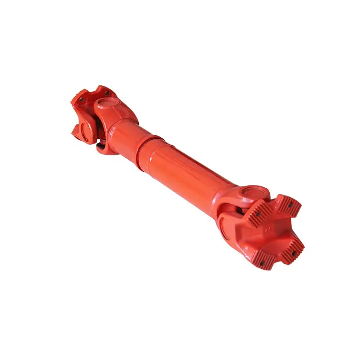
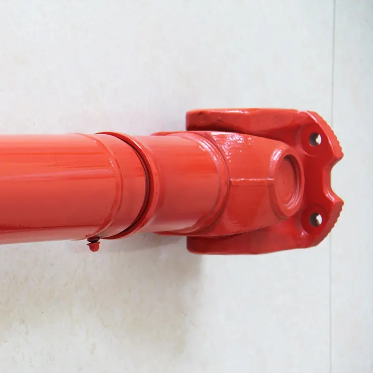
Product Description
SWC Cardan Shaft for Skew Roliing Mill Machinery
Who we are?
HangZhou XIHU (WEST LAKE) DIS. CARDANSHAFT CO;LTD has 15 years history.When the general manager Mr.Rony Du graduated from the university,he always concentrated his attention on the research and development,production and sales of the cardan shaft.Mr.Rony Du and his team started from scratch,from 1 lathe and a very small order,step by step to grow up.He often said to his team”We will only do 1 thing well——to make the perfect cardan shaft”.
HangZhou XIHU (WEST LAKE) DIS. CARDANSHAFT CO.,LTD was founded in 2005.The registered capital is 8 million ,covers an area of 15 acres, has 30 existing staff. The company specializing in the production of SWC, SWP cross universal coupling and drum tooth coupling.The company with factory is located in the beautiful coast of Tai Lake –Hudai (HangZhou Economic Development Zone Hudai Industrial Park).
In order to become China’s leading cardan shaft one-stop solution expert supplier .XIHU (WEST LAKE) DIS. CARDANSHAFT independent research and development of SWC light, medium, short, heavy Designs cardan shaft have reached the leading domestic level.Products not only supporting domestic large and medium-sized customers, but also exported to the United States, India, Vietnam, Laos, Ukraine, Russia, Germany, Britain and other countries and areas.In the past 15 years, the company has accumulated a wealth of experience, learn from foreign advanced technology, and to absorb and use the universal axis has been improved several times, so that the structure is maturing, significantly improved performance.
XIHU (WEST LAKE) DIS. belief: “Continuous innovation, optimize the structure, perseverance” to create a high quality of outstanding cardan shaft manufacturer.We always adhere to the ISO9001 quality control system, from the details to start, standardize the production process, and to achieve processing equipment “specialization, numerical control” rapid increase in product quality.This Not only won the majority of customers reputation, but also access to peer recognition. We continue to strive to pursue: “for customers to create the greatest value, for the staff to build the best platform”, will be able to achieve customer and business mutually beneficial CHINAMFG situation.
Why choose us?
First,select raw material carefully
The cross is the core component of cardan shaft,so the selection of material is particularly critical.Raw materials of the cross for light Duty Size and Medium Duty Size,we choose the 20CrMnTi special gear steel bar from SHAGANG GROUP.Being forged in 2500 ton friction press to ensure internal metallurgical structure,inspecting the geometric dimensions of each part to meet the drawing requirements,then transfer to machining,the processes of milling, turning, quenching and grinding.
The inspector will screen blank yoke head.The porosity, cracks, slag, etc. do not meet the requirements of the casting foundry are all eliminated,then doing physical and chemical analysis, to see whether the ingredients meet the requirements, unqualified re-elimination.And then transferred to the quenching and tempering heat treatment, once again check the hardness to see if meet the requirements, qualified to be transferred to the machining process. We control from the source of the material to ensure the supply of raw materials qualified rate of 99%.
Second,advanced production equipment
XIHU (WEST LAKE) DIS. Company introduced four-axis linkage machining center made in ZheJiang , milling the keyway and flange bolt hole of the flange yoke, The once machine-shaping ensures that the symmetry of the keyway and the position of the bolt hole are less than 0.02mm,which greatly improves the installation accuracy of the flange,the 4 axis milling and drilling center holes of the cross are integrated,to ensure that the 4 shaft symmetry and verticality are less than 0.02mm,the process of the journal cross assembly service life can be increased by 30%, and the speed at 1000 rpm above the cardan shaft running smoothly and super life is crucial to the operation.
We use CNC machine to lathe flange yoke and welded yoke,CNC machine can not only ensure the accuracy of the flange connection with the mouth, but also improve the flange surface finish.
5 CHINAMFG automatic welding machine welding spline sleeve and tube,welded yoke and tube.With the welding CHINAMFG swing mechanism, automatic lifting mechanism, adjustment mechanism and welding CHINAMFG cooling system, welding machine can realize multi ring continuous welding, each coil current and voltage can be preset, arc starting and stopping control PLC procedures, reliable welding quality, the weld bead is smooth and beautiful, to control the welding process with fixed procedures, greatly reducing the uncertainty of human during welding, greatly improve the welding effect.
High speed cardan shaft needs to do dynamic balance test before leaving the factory.Unbalanced cardan shaft will produce excessive centrifugal force at high speed and reduce the service life of the bearing;the dynamic balance test can eliminate the uneven distribution of the casting weight and the mass distribution of the whole assembly;Through the experiment to achieve the design of the required balance quality, improve the universal shaft service life.In 2008 the company introduced 2 high-precision dynamic balance test bench, the maximum speed can reach 4000 rev / min, the balance of G0.8 accuracy, balance weight 2kg–1000kg.
In order to make the paint standardization, in 2009 the company bought 10 CHINAMFG of clean paint room , the surface treatment of cardan shaft is more standardized, paint fastness is more rugged, staff’s working conditions improved, exhaust of harmless treatment.
Third,Professional transport packaging
The packing of the export cardan shaft is all in the same way as the plywood wooden box, and then it is firmly secured with the iron sheet, so as to avoid the damage caused by the complicated situation in the long-distance transportation. Meet the standard requirements of plywood boxes into Europe and other countries, no matter where can successfully reach all the country’s ports.
The following table for SWC Medium-sized Universal Shaft Parameters.
Designs
Data and Sizes of SWC Series Universal Joint Couplings
| pe | Design Data Item |
SWC160 | SWC180 | SWC200 | SWC225 | SWC250 | SWC265 | SWC285 | SWC315 | SWC350 | SWC390 | SWC440 | SWC490 | SWC550 | SWC620 |
| A | L | 740 | 800 | 900 | 1000 | 1060 | 1120 | 1270 | 1390 | 1520 | 1530 | 1690 | 1850 | 2060 | 2280 |
| LV | 100 | 100 | 120 | 140 | 140 | 140 | 140 | 140 | 150 | 170 | 190 | 190 | 240 | 250 | |
| M(kg) | 65 | 83 | 115 | 152 | 219 | 260 | 311 | 432 | 610 | 804 | 1122 | 1468 | 2154 | 2830 | |
| B | L | 480 | 530 | 590 | 640 | 730 | 790 | 840 | 930 | 100 | 1571 | 1130 | 1340 | 1400 | 1520 |
| M(kg) | 44 | 60 | 85 | 110 | 160 | 180 | 226 | 320 | 440 | 590 | 820 | 1090 | 1560 | 2100 | |
| C | L | 380 | 420 | 480 | 500 | 560 | 600 | 640 | 720 | 782 | 860 | 1040 | 1080 | 1220 | 1360 |
| M(kg) | 35 | 48 | 66 | 90 | 130 | 160 | 189 | 270 | 355 | 510 | 780 | 970 | 1330 | 1865 | |
| D | L | 520 | 580 | 620 | 690 | 760 | 810 | 860 | 970 | 1030 | 1120 | 1230 | 1360 | 1550 | 1720 |
| M(kg) | 48 | 65 | 90 | 120 | 173 | 220 | 250 | 355 | 485 | 665 | 920 | 1240 | 1765 | 2390 | |
| E | L | 800 | 850 | 940 | 1050 | 1120 | 1180 | 1320 | 1440 | 1550 | 1710 | 1880 | 2050 | 2310 | 2540 |
| LV | 100 | 100 | 120 | 140 | 140 | 140 | 140 | 140 | 150 | 170 | 190 | 190 | 240 | 250 | |
| M(kg) | 70 | 92 | 126 | 165 | 238 | 280 | 340 | 472 | 660 | 886 | 1230 | 1625 | 2368 | 3135 | |
| Tn(kN·m) | 16 | 22.4 | 31.5 | 40 | 63 | 80 | 90 | 125 | 180 | 250 | 355 | 500 | 710 | 1000 | |
| TF(kN·m) | 8 | 11.2 | 16 | 20 | 31.5 | 40 | 45 | 63 | 90 | 125 | 180 | 250 | 355 | 500 | |
| Β(°) | 15 | 15 | 15 | 15 | 15 | 15 | 15 | 15 | 15 | 15 | 15 | 15 | 15 | 15 | |
| D | 160 | 180 | 200 | 225 | 250 | 265 | 285 | 315 | 350 | 390 | 440 | 490 | 550 | 620 | |
| Df | 160 | 180 | 200 | 225 | 250 | 265 | 285 | 315 | 350 | 3690 | 440 | 490 | 550 | 620 | |
| D1 | 137 | 155 | 170 | 196 | 218 | 233 | 245 | 280 | 310 | 345 | 390 | 435 | 492 | 555 | |
| D2(H9) | 100 | 105 | 120 | 135 | 150 | 160 | 170 | 185 | 210 | 235 | 255 | 275 | 320 | 380 | |
| D3 | 108 | 114 | 140 | 159 | 168 | 180 | 194 | 219 | 245 | 273 | 299 | 325 | 402 | 426 | |
| Lm | 95 | 105 | 110 | 125 | 140 | 150 | 160 | 180 | 195 | 215 | 260 | 270 | 305 | 340 | |
| K | 16 | 17 | 18 | 20 | 25 | 25 | 27 | 32 | 35 | 40 | 42 | 47 | 50 | 55 | |
| T | 4 | 5 | 5 | 5 | 6 | 6 | 7 | 8 | 8 | 8 | 10 | 12 | 12 | 12 | |
| N | 8 | 8 | 8 | 8 | 8 | 8 | 8 | 10 | 10 | 10 | 16 | 16 | 16 | 16 | |
| D | 15 | 17 | 17 | 17 | 19 | 19 | 21 | 23 | 23 | 25 | 28 | 31 | 31 | 38 | |
| B | 20 | 24 | 32 | 32 | 40 | 40 | 40 | 40 | 50 | 70 | 80 | 90 | 100 | 100 | |
| G | 6.0 | 7.0 | 9.0 | 9.0 | 12.5 | 12.5 | 12.5 | 15.0 | 16.0 | 18.0 | 20.0 | 22.5 | 22.5 | 25 | |
| MI(Kg) | 2.57 | 3 | 3.85 | 3.85 | 5.17 | 6 | 6.75 | 8.25 | 10.6 | 13 | 18.50 | 23.75 | 29.12 | 38.08 | |
| Size | M14 | M16 | M16 | M16 | M18 | M18 | M20 | M22 | M22 | M24 | M27 | M30 | M30 | M36 | |
| Tightening torque(Nm) | 180 | 270 | 270 | 270 | 372 | 372 | 526 | 710 | 710 | 906 | 1340 | 1820 | 1820 | 3170 |
1. Notations:
L=Standard length, or compressed length for designs with length compensation;
LV=Length compensation;
M=Weight;
Tn=Nominal torque(Yield torque 50% over Tn);
TF=Fatigue torque, I. E. Permissible torque as determined according to the fatigue strength
Under reversing loads;
Β=Maximum deflection angle;
MI=weight per 100mm tube
2. Millimeters are used as measurement units except where noted;
3. Please consult us for customizations regarding length, length compensation and
Flange connections.
(DIN or SAT etc. )
Brief Introduction
Processing flow
Applications
Quality Control
/* March 10, 2571 17:59:20 */!function(){function s(e,r){var a,o={};try{e&&e.split(“,”).forEach(function(e,t){e&&(a=e.match(/(.*?):(.*)$/))&&1
| Material: | Alloy Steel |
|---|---|
| Load: | Drive Shaft |
| Stiffness & Flexibility: | Stiffness / Rigid Axle |
| Journal Diameter Dimensional Accuracy: | IT6-IT9 |
| Axis Shape: | Straight Shaft |
| Shaft Shape: | Hollow Axis |
| Customization: |
Available
| Customized Request |
|---|
What factors should be considered when selecting the right cardan shaft for an application?
When selecting a cardan shaft for a specific application, several crucial factors need to be considered to ensure optimal performance and longevity. The following factors should be taken into account during the selection process:
1. Torque Requirements:
– One of the primary considerations is the torque requirements of the application. The cardan shaft should be capable of transmitting the required torque without exceeding its rated capacity. It is essential to determine the maximum torque that the shaft will experience during operation and select a cardan shaft that can handle that torque while providing an appropriate safety margin.
2. Speed and RPM:
– The rotational speed or RPM (revolutions per minute) of the application is another critical factor. Cardan shafts have specific rotational speed limits, and exceeding these limits can lead to premature wear, vibration, and failure. It is crucial to select a cardan shaft that is rated for the speed requirements of the application to ensure reliable and smooth operation.
3. Angle of Misalignment:
– The angle of misalignment between the driving and driven components should be considered. Cardan shafts can accommodate angular misalignment up to a certain degree, typically specified by the manufacturer. It is important to select a cardan shaft that can handle the anticipated misalignment angle to ensure proper power transmission and prevent excessive wear or binding.
4. Operating Conditions:
– The operating conditions of the application play a vital role in cardan shaft selection. Factors such as temperature, humidity, presence of corrosive agents, and exposure to vibration or shock need to be considered. It is crucial to select a cardan shaft that is designed to withstand the specific operating conditions to ensure durability and reliability.
5. Length and Size:
– The length and size of the cardan shaft should be chosen appropriately for the application. The length of the shaft affects its ability to absorb vibrations and accommodate misalignments. It is important to consider the available space and the required length to ensure proper fitment and functionality. Additionally, the size of the cardan shaft should be selected based on the load requirements and the available torque capacity.
6. Maintenance and Serviceability:
– Consideration should be given to the ease of maintenance and serviceability of the cardan shaft. Some applications may require regular inspection, lubrication, or replacement of certain components. It is beneficial to select a cardan shaft that allows convenient access for maintenance and incorporates features such as grease fittings or easily replaceable universal joints.
7. Cost and Budget:
– Finally, the cost and budget constraints should be taken into account. Different cardan shaft manufacturers and suppliers may offer varying prices for their products. It is important to balance the desired quality, performance, and durability of the cardan shaft with the available budget.
By carefully considering these factors, engineers and designers can select the right cardan shaft for the application, ensuring optimal performance, longevity, and reliability. Collaboration with cardan shaft manufacturers and suppliers can also provide valuable insights and assistance in making the appropriate selection based on the specific requirements of the application.
Can you provide real-world examples of vehicles and machinery that use cardan shafts?
Cardan shafts are widely used in various vehicles and machinery across different industries. They are employed in applications where torque transmission, power distribution, and flexibility are crucial. Here are some real-world examples of vehicles and machinery that utilize cardan shafts:
1. Automotive Vehicles:
– Cars, trucks, and SUVs: Cardan shafts are commonly found in rear-wheel drive (RWD) and four-wheel drive (4WD) vehicles. They connect the transmission or transfer case to the rear differential or front differential, respectively, enabling torque transmission to the wheels. Examples include sedans, pickup trucks, and SUVs like Jeep Wrangler, Ford F-150, and Toyota Land Cruiser.
– Buses and commercial vehicles: Cardan shafts are used in buses and commercial vehicles that have rear-wheel drive or all-wheel drive configurations. They transmit torque from the engine or transmission to the rear axle or multiple axles. Examples include city buses, coaches, and delivery trucks.
2. Off-Road and Utility Vehicles:
– Off-road vehicles: Many off-road vehicles, such as off-road trucks, SUVs, and all-terrain vehicles (ATVs) utilize cardan shafts. These shafts provide the necessary torque transfer and power distribution to all wheels for improved traction and off-road capabilities. Examples include the Land Rover Defender, Jeep Wrangler Rubicon, and Yamaha Grizzly ATV.
– Agricultural machinery: Farm equipment like tractors and combine harvesters often employ cardan shafts to transmit power from the engine to various attachments such as mowers, balers, and harvesters. The shafts enable efficient power distribution and flexibility for different agricultural tasks.
– Construction and mining machinery: Equipment used in construction and mining applications, such as excavators, loaders, and bulldozers, utilize cardan shafts to transfer power from the engine or transmission to the different components of the machinery. These shafts enable power distribution and torque transmission to various attachments, allowing for efficient operation in demanding environments.
3. Industrial Machinery:
– Manufacturing machinery: Cardan shafts are used in industrial equipment such as conveyors, mixers, and rotary equipment. They provide torque transmission and power distribution within the machinery, enabling efficient operation and movement of materials.
– Paper and pulp industry: Cardan shafts are employed in paper and pulp processing machinery, including paper machines and pulp digesters. These shafts facilitate power transmission and torque distribution to various parts of the machinery, contributing to smooth operation and high productivity.
– Steel and metal processing machinery: Equipment used in steel mills and metal processing facilities, such as rolling mills, extruders, and coil winding machines, often utilize cardan shafts. These shafts enable power transmission and torque distribution to the different components involved in metal forming, shaping, and processing.
These examples represent just a few of the many applications where cardan shafts are employed. Their versatility, durability, and ability to handle torque transmission and power distribution make them essential components in a wide range of vehicles and machinery across industries.

Can you explain the components and structure of a cardan shaft system?
A cardan shaft system, also known as a propeller shaft or drive shaft, consists of several components that work together to transmit torque and rotational power between non-aligned components. The structure of a cardan shaft system typically includes the following components:
1. Shaft Tubes:
– The shaft tubes are the main structural elements of a cardan shaft system. They are cylindrical tubes made of durable and high-strength materials such as steel or aluminum alloy. The shaft tubes provide the backbone of the system and are responsible for transmitting torque and rotational power. They are designed to withstand high loads and torsional forces without deformation or failure.
2. Universal Joints:
– Universal joints, also known as U-joints or Cardan joints, are crucial components of a cardan shaft system. They are used to connect and articulate the shaft tubes, allowing for angular misalignment between the driving and driven components. Universal joints consist of a cross-shaped yoke with needle bearings at each end. The yoke connects the shaft tubes, while the needle bearings enable the rotational motion and flexibility required for misalignment compensation. Universal joints allow the cardan shaft system to transmit torque even when the driving and driven components are not perfectly aligned.
3. Slip Yokes:
– Slip yokes are components used in cardan shaft systems that can accommodate axial misalignment. They are typically located at one or both ends of the shaft tubes and provide a sliding connection between the shaft and the driving or driven component. Slip yokes allow the shaft to adjust its length and compensate for changes in the distance between the components. This feature is particularly useful in applications where the distance between the driving and driven components can vary, such as vehicles with adjustable wheelbases or machinery with variable attachment points.
4. Flanges and Yokes:
– Flanges and yokes are used to connect the cardan shaft system to the driving and driven components. Flanges are typically bolted or welded to the ends of the shaft tubes and provide a secure connection point. They have a flange face with bolt holes that align with the corresponding flange on the driving or driven component. Yokes, on the other hand, are cross-shaped components that connect the universal joints to the flanges. They have holes or grooves that accommodate the needle bearings of the universal joints, allowing for rotational motion and torque transfer.
5. Balancing Weights:
– Balancing weights are used to balance the cardan shaft system and minimize vibrations. As the shaft rotates, imbalances in the mass distribution can lead to vibrations, noise, and reduced performance. Balancing weights are strategically placed along the shaft tubes to counterbalance these imbalances. They redistribute the mass, ensuring that the rotational components of the cardan shaft system are properly balanced. Proper balancing improves stability, reduces wear on bearings and other components, and enhances the overall performance and lifespan of the shaft system.
6. Safety Features:
– Some cardan shaft systems incorporate safety features to protect against mechanical failures. For example, protective guards or shielding may be installed to prevent contact with rotating components, reducing the risk of accidents or injuries. In applications where excessive forces or torques can occur, cardan shaft systems may include safety mechanisms such as shear pins or torque limiters. These features are designed to protect the shaft and other components from damage by shearing or disengaging in case of overload or excessive torque.
In summary, a cardan shaft system consists of shaft tubes, universal joints, slip yokes, flanges, and yokes, as well as balancing weights and safety features. These components work together to transmit torque and rotational power between non-aligned components, allowing for angular and axial misalignment compensation. The structure and components of a cardan shaft system are carefully designed to ensure efficient power transmission, flexibility, durability, and safety in various applications.


editor by CX 2024-02-06